PRODUCTS CATEGORY
HOT PRODUCT
Contact Us
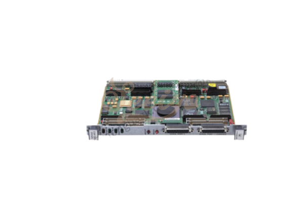
MOTOROLA MVME166 Single Board Computer
Description
.Many products are not yet on the shelves please contact us for more products
.If there is any inconsistency between the product model and the picture on display, the model shall prevail. Contact us for the specific product picture, and we will arrange to take photos in the warehouse for confirmation
.We have 16 shared warehouses around the world, so please understand that it can sometimes take several hours to accurately return to you. Of course, we will respond to your concerns as soon as possible
MOTOROLA MVME166 Single Board Computer All programmable registers in the MVME166 that reside in ASICs are covered in the MVME166/MVME167/MVME187 Single Board Computers Programmer’s Reference Guide
The MVME166 is based on the MC68040 microprocessor. The MVME166 has 4/8/16/32/64/128/2 56 MB o f ECC-protected D RAM, 1 MB of Flash mem ory with download EPROM, 128KB of static RAM (with battery backup), 8KB of static RAM and time of day clock (with battery backup), Ethernet transceiver interface, four serial ports with TTL inter face, four tick timers, watchdog timer, SCSI bus interface with DMA, Centronics printer port, A16/A24/A32/D8/D16/D32/D64 VMEbus master/slave interface, VMEbus system controller, and a VSB interface.
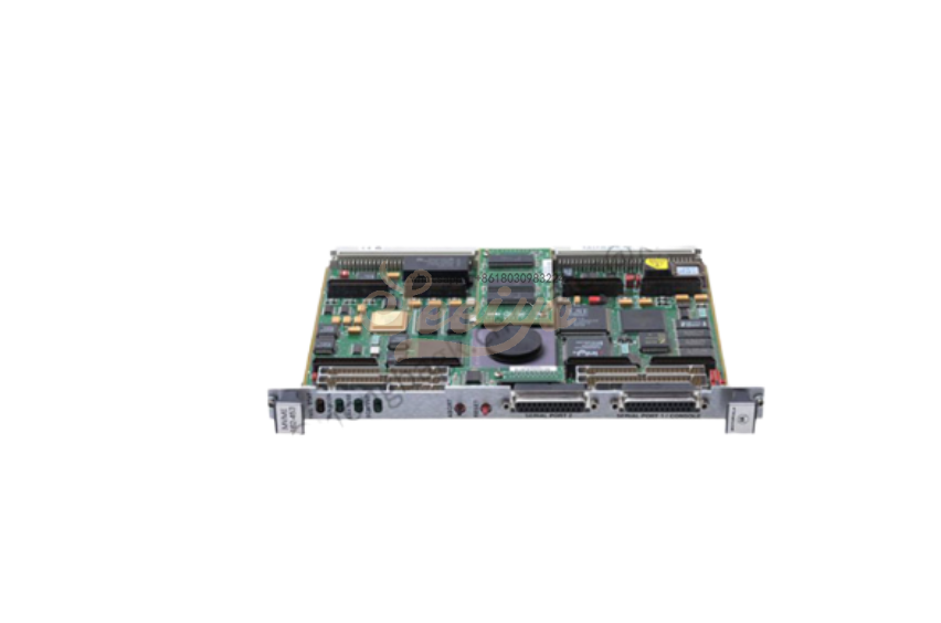
The I/O connection for the MVME166 is provided by two high density shielded front panel I/O connectors. The SCSI bus is connected through a 68 pin connector. The printer, four serial ports and Ethernet interface are connected through a 100 pin con n ecto r. The MVME712-10 transition mo dul e and the MVME712-06/07/09 I/O distribution board set were designed to support the MVME166 boards. These transition boards provide configuration headers, serial port drivers and industry standard connectors for the I/O devices.
The VMEbus interface is provided by an ASIC called the VMEchip2. The VMEchip2 includes two tick timers, a watchdog timer, programmable map decoders for the master and slave interfaces, and a VME bus to/from local bus DMA controller, a VMEbus to/from local bus non-DMA programmed access interface, a VMEbus interrupter, a VMEbus system controller, a VMEbus interrupt handler, and a VMEbus requester.
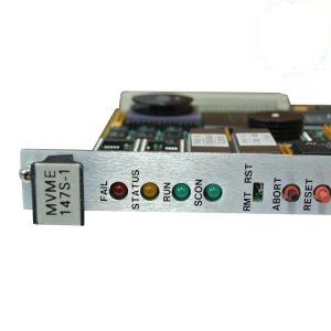
There are switches and LEDs on the front panel of the MVME166. The switches are RESET and ABORT. The RESET switch resets all onboard devices and drives SYSRESET* if the board is system controller. The RESET switch may be disabled by software. When enabled by software, the ABORT switch generates an interrupt at a user-programmable level. It is normally used to abort program execution and return to the debugger. There are ten LEDs on the MVME166 front panel: FAIL, STAT, RUN, SCON, LAN, RPWR, SCSI, VME, TPWR and VSB. The red FAIL LED (part of DS1) lights when the BRDFAIL signal line is active. The MC68040 status lines are decoded, on the MVME166, to drive the yellow STAT (status) LED (part of DS1). In this case, a halt condition from the processor lights the LED. The green RUN LED (part of DS2) lights when the local bus TIP* signal line is low. This indicates one of the local bus masters is executing a local bus cycle. The green SCON LED (part of DS2) lights when the VMEchip2 in the MVME166 is the VMEbus system controller. The green LAN LED (part of DS3) lights when the LAN chip is local bus master. The MVME166 supplies +5V, +12V, and -12V power to the transition board through fuses. There is one fuse for each voltage. The green RPWR (remote power) LED (part of DS3) lights when all three voltages are available to the transition board interface. The green SCSI LED (part of DS4) lights when the SCSI chip is local bus master. The green VME LED (part of DS4) lights when the board is using the VMEbus (VMEbus AS* is asserted by the VMEchip2) or when the board is accessed by the VMEbus (VMEchip2 is the local bus master). The MVME166 supplies +5V to the SCSI bus for terminator power through a fuse. The green TPWR (terminator power) LED (part of DS5) lights when TERMPWR is available to the SCSI bus. SCSI bus TERMPWR may be supplied by other devices on the SCSI bus. The green VSB LED (part of DS5) lights when the MVME166 is using the VSB (VSB PAS* is asserted by the VSBchip2) or when the MVME166 is accessed by the VSB (VSBchip2 is the local bus master).
| Mailbox:josephine@seeiyo.com | MOTOROLA MVME166 Single Board |
| www.seeiyo.com | +86 18030983224 |


