PRODUCTS CATEGORY
HOT PRODUCT
Contact Us
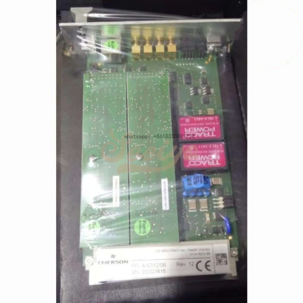
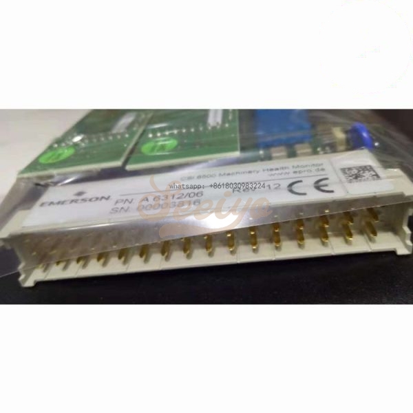
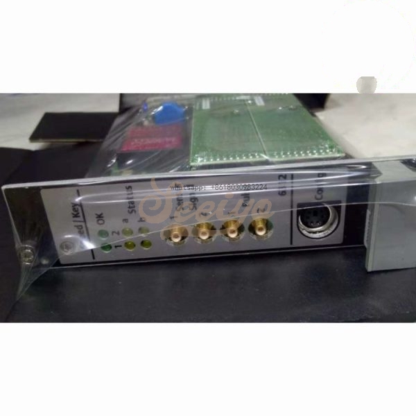
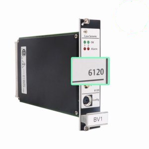
EMERSON A6312 9199-00024 Speed/Key Module (8HP)
Description
.Many products are not yet on the shelves please contact us for more products
.If there is any inconsistency between the product model and the picture on display, the model shall prevail. Contact us for the specific product picture, and we will arrange to take photos in the warehouse for confirmation
.We have 16 shared warehouses around the world, so please understand that it can sometimes take several hours to accurately return to you. Of course, we will respond to your concerns as soon as possible
EMERSON A6312 9199-00024 Speed/Key Module (8HP) A6312/06 A6312/08 Goods size : 9.5 x 6.75 x 2.5 cm; 13.6oz.In addition, damaged equipment is expensive and time-consuming to repair or replace. During transient and normal operation, the AMS 6300 SIS guards against overspeed conditions caused by sudden load loss and unexpected changes.


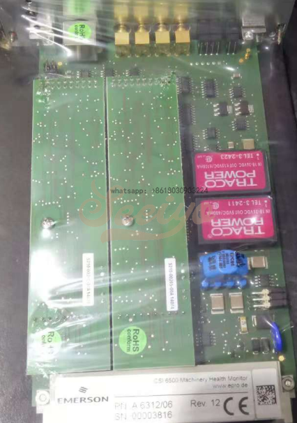
CSI 6500 Machinery Health Monitor A6312, Dual Channel Speed/ Key Monitor
The two−channel rotational speed monitor A6312 is a module of the A6000 machine monitoringsystem. The micro−processor controlled monitor is used in conjunction with two eddy currentmeasuring chains or hall−effect sensors (e.g. PR 9376) and in combination with triggeringwheels to measure and conditioning of shaft speeds and rotational reference marks(key−pulses).Both channels may be used separately used to measure:
•2 speeds from 2 shafts2 key−pulses from 2 shafts each with a triggermark (with phase relation)
•Both channels may also be used in combination with each other:to detect the direction of rotation of one shaft
•to detect a difference between two shaft speeds

A prepared 3U slot in a 19" rack, or other Intermas−compatible enclosure, is required formounting the A6312 monitor. The slot must be fitted with a 48−pin plug connector (DIN 41612,design F 48 M). The pin assignment is listed in the following table.
Jumper RS 485
RS 485 bus operation requires an electrical terminator on the first and last bus device.This is done with plug−in jumpers, that are on the controller board. The figure shows the positionof the jumpers
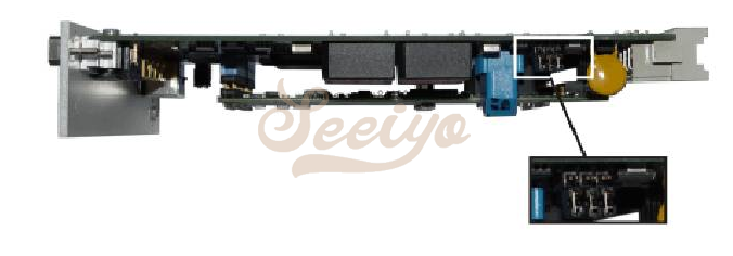
To activate the bus terminator and to place lines "A" and "B" on the references, plug the jumpersas shown in Fig. b). Fig. a) shows the jumper position for deactivated bus termination and openreferences (delivery status).


